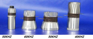
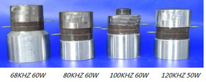
1 Photo Reference
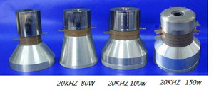
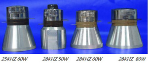
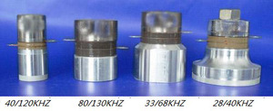
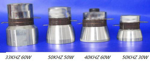
2 Technical Parameters
Can supply different ultrasonic cleaning soultion .please contact us for more details
Type | Frequency (KHz) | Capacitance (pF) | Impedance (Ω) | Dimension D*H | Power (W) | SIR (2500VDC) | Notes |
GPC-8SS-2540 | 40±0.8 | 3100±10% | ≤30Ω | 25*58 | 20w | ≥100MΩ |
Yellow chip |
GPC-8SS-3045 | 46±1.0 | 2400±10% | ≤25Ω | 45*43 | 35w | ≥100MΩ |
GPC-8SH-3517 | 17±1.0 | 2550±10% | ≤28Ω | 78*93 | 50w | ≥100MΩ |
GPC-8SH-3820 | 20±0.8 | 3800±10% | ≤28Ω | 59*99 | 60w | ≥100MΩ |
GPC-8SH-3823 | 23±0.8 | 3800±10% | ≤28Ω | 59*84 | 60w | ≥100MΩ |
GPC-8SH-3825* | 25±0.8 | 3800±10% | ≤20Ω | 59*80 | 60w | ≥100MΩ |
GPC-8SH-3828* | 28±0.5 | 3800±10% | ≤20Ω | 59*68 | 60w | ≥100MΩ |
GPC-8SH-3833* | 33±0.5 | 3800±10% | ≤20Ω | 48*61 | 60w | ≥100MΩ |
GPC -8SH-3840* | 40±0.5 | 3800±10% | ≤20Ω | 48*51 | 60w | ≥100MΩ |
GPC-8SH-4520* | 21.5±0.8 | 5600±10% | ≤20Ω | 67*92 | 80w | ≥100MΩ |
GPC-8SH-4528* | 28±0.5 | 5600±10% | ≤20Ω | 67*68 | 80w | ≥100MΩ |
GPC-8SH-5028 | 28±0.5 | 7200±10% | ≤20Ω | 67*68 | 100w | ≥100MΩ |
GPC-8SH-5020 | 20±0.5 | 4650±10% | ≤25Ω | 79*94 | 120w | ≥100MΩ |
GPC-8SH-2020(5X4) | 20±0.5 | 5000±10% | ≤25Ω | 35*89 | 60w | ≥100MΩ | High power series |
GPC-8SH-3020(5X4) | 20±0.5 | 7000±10% | ≤20Ω | 45*88 | 80w | ≥100MΩ |
GPC-8SH-4020(5X4) | 20±0.5 | 10000±10% | ≤15Ω | 54*88 | 120w | ≥100MΩ |
GPC-8SH-4520(5X4) | 20±0.5 | 14500±10% | ≤12Ω | 64*88 | 160w | ≥100MΩ |
GPC-8SH-5020(5X4) | 20±0.5 | 18000±10% | ≤10Ω | 74*88 | 200w | ≥100MΩ |
GPC-4AS-1550 | 51.0±2.0 | 1700±10% | ≤50Ω | 15*58 | 10W | ≥100MΩ |
Black chip |
GPC-4AS-1540(2.5X4) | 40±2.0 | 3400±10% | ≤30Ω | 15*58 | 15W | ≥100MΩ |
GPC-4SS-2540 | 40±0.8 | 2400±10% | ≤30Ω | 25*58 | 20w | ≥100MΩ |
GPC-4SH-2540 | 40±0.8 | 2400±10% | ≤30Ω | 30*50 | 20w | ≥100MΩ |
GPC-4AH-2560 | 60±1.5 | 2300±10% | ≤35Ω | 30*35 | 20w | ≥100MΩ |
GPC-4AS-2565 | 65±1.5 | 2300±10% | ≤35Ω | 25*31 | 20w | ≥100MΩ |
GPC-4AS-3055 | 55±1.0 | 3100±10% | ≤35Ω | 30*45 | 35w | ≥100MΩ |
GPC-4AH-3050 | 52±2.0 | 3100±10% | ≤35Ω | 38*40 | 35w | ≥100MΩ |
GPC-4SS-3528* | 28 ±0.5 | 4000±10% | ≤20Ω | 45*79 | 50w | ≥100MΩ |
GPC-4AH-3540* | 40 ±1.0 | 4000±10% | ≤20Ω | 45*55 | 50w | ≥100MΩ |
GPC-4SH-3825* | 25±0.8 | 5100±10% | ≤20Ω | 59*80 | 60w | ≥100MΩ |
GPC-4SH-3828* | 28±0.5 | 5100±10% | ≤20Ω | 59*68 | 60w | ≥100MΩ |
GPC-4SS-3833 | 33±0.5 | 5100±10% | ≤20Ω | 48*62 | 60w | ≥100MΩ |
GPC-4SS-3835 | 35±0.5 | 5100±10% | ≤20Ω | 45*55 | 60w | ≥100MΩ |
GPC-4SH-3840* | 40±0.5 | 5100±10% | ≤20Ω | 48*51 | 60w | ≥100MΩ |
GPC-4SH-4520 | 22±0.5 | 7600±10% | ≤20Ω | 67*92 | 80w | ≥100MΩ |
GPC-4SH-4525 | 25±0.5 | 7600±10% | ≤20Ω | 67*76 | 80w | ≥100MΩ |
GPC-4SH-4528* | 28±0.5 | 7600±10% | ≤20Ω | 67*68 | 80w | ≥100MΩ |
GPC-4SH-5028 | 28±0.5 | 9600±10% | ≤20Ω | 67*68 | 100w | ≥100MΩ |
GPC-4SS-3868 | 67±2.0 | 5100±10% | ≤20Ω | 50*65 | 50w | ≥100MΩ | complex frequency |
GPC-4SS-3880** | 79±1.5 | 4200±10% | ≤25Ω | 40*54 | 60w | ≥100MΩ |
GPC-4SS-38100 | 100±1.5 | 5100±10% | ≤25Ω | 40*57 | 60w | ≥100MΩ |
GPC-4AS-38120** | 120±1.5 | 5100±10% | ≤25Ω | 40*58 | 60w | ≥100MΩ |
GPC-4SS-38130** | 129±1.5 | 4200±10% | ≤25Ω | 40*54 | 60w | ≥100MΩ |
GPC-4SS-38160** | 160±1.5 | 5100±10% | ≤25Ω | 40*57 | 60w | ≥100MΩ |
GPC-4AS-35165 | 165±5.0 | 4100±10% | ≤60Ω | 42*61 | 40w | ≥100MΩ |
GPC-4AH-25200 | 200±2.0 | 2300±10% | ≤35Ω | 30*35 | 20w | ≥100MΩ |
GPC-4AS-35235 | 235±5.0 | 4100±10% | ≤60Ω | 42*61 | 30w | ≥100MΩ |
GPC-8SE-3828/40 | 28/40±1.0 | 3800±10% | ≤30Ω | 65*70 | 60w | ≥100MΩ |
Multy frequency |
GPC-8SS-2540/130 | 40/130±2.0 | 3100±10% | ≤30Ω | 25*58 | 20w | ≥100MΩ |
GPC-4SS-3840/68 | 38/66±2.0 | 5100±10% | ≤20Ω | 50*65 | 50w | ≥100MΩ |
GPC-4SS-3840/80/130 | 38/79/128±2 | 4200±10% | ≤25Ω | 40*54 | 60w | ≥100MΩ |
GPC-4SS-3840/100/160 | 38/100/160±2.0 | 5100±10% | ≤25Ω | 40*57 | 60w | ≥100MΩ |
Note:
1.Label“*”isregular type,generally have inventory stock。
2.For installationof the front cover is installed with screw, screw size (diameter * toothdistance * depth) are M10 * 1.0 * 10, few of them note "**" arefor the M10 * 1.5 * 10.
3 Design Principles
Theultrasonic cleaning transducer usually adopts horn-type composite oscillatorstructure (belonging to Langevin oscillator structure), which consists of frontand rear metal cover, piezoelectric ceramic chips, pre-stressed screw,electrode slice, and insulating sleeve. Imposed by appropriate pre-stress, thetransducer has good mechanical and electrical conversion efficiency under highpower and large-amplitude conditions.
It is through the ultrasonic vibration-wave of thetransducer occurring cavitations in the water and generates high-pressurevacuole to impact the cleaning materials, so as to achieve an excellentcleaning effect.
The ultrasonic cleaning transducer is a medium-powertransducer that can work continuously. Generally, the power value is calculatedaccording to the average of continuous and constant work.
Frequently Asked Questions
Q: How to judge positive and negative electrodes ofthe transducers?
A.The electrode located between the two piezoelectric chips is positive.
Q: The insulation method of the transducer?
A:Parallel connection; pull the wire through the hole and need to be welded withtin; make sure to avoid lap welding.
Q: How to opt suitable wires that connected to thetransducer?
A:Adopt soft enough silicone wire, around 1.2 square diameters.
Q: How to insulation method of the transducer.
A:Exposed wires and soldered positions need to be sealed with heat-shrinkabletube and silicone glue.
Q: How to test the insulation of the transducer?
A:Use a megohm meter around 1500V to test the insulation impedance of thepositive and negative electrodes; required greater than 50MΩ, except for highhumidity environments.
Q: What’s the meaning of the parameters oftransducer?
A: Free capacitance CT=C0+C1,”C0” refer to the static capacitance, “C1”for the dynamic capacitance; “Dt” for the dielectric loss; “fs” for the seriesresonant frequency, “fp” for parallel resonant frequency and the frequencybandwidth “fsp” = fp-fs; bandwidth “f12” = f2-f1, “f1” and “f2” respectivelycorresponding to the left and right point of the half-power bandwidth; “R1”refers to the dynamic impedance; “L1” for the dynamic inductance; “Zr” or“Zmin” for the parallel resonant impedance; “Zmax” for the series resonantimpedance; “Qm” for the mechanical quality factor; “Keff” for the couplingcoefficient.
Q: Transducers are grouped as per what order ofparameter?
A:Transducers of our company are classified as per the order of frequency,capacitance and then impedance.
Q: What’s the definition of the power of transducer?
A:Ultrasonic cleaning transducer is generally rated average power. It’s definedas the maximum input power upon resonant frequency.
Q: What’s the definition of the power of washingmachine?
A:Washing machine power, usually defined as the geometric product of thetransducer numbers with rated power, which is known as the nominal power. Butthe input electric power is less than nominal power.
Q: Why the input electric power is lower than thepower of the washing machine?
A:A single transducer power is the maximum power upon resonant frequency. Once anumber of transducers are in parallel, the total frequency may deviate from theresonance frequency of a single transducer due to the consistency and adhesivetechniques of the transducer. It means that the transducers can’t work underthe best frequency, so the total input electric power is lower than the nominalpower of the washing machine. The more transducers are in parallel, the greaterdeviation between the two powers.
Q: Option of the power of the washing machine.
A:The power of washing machine is determined by the size of cleaning containerand arrangement of transducers, usually calculated according to the powerdensity 0.5-0.6w/cm2.
Q: How to arrange the transducers for the washingmachine?
A:Transducer-arrangement depends on the structure of cleaning container and theeffective distance of different frequency, and then substitutes thepower-density into formula to calculate the number and get an integer.
Q: Why there are multiple frequencies when debug themachine?
A:When the transducer is being debugged, there’re four frequencies around theresonance point under a strong electric field. The lower one is the lateralvibration-frequency of oscillator, followed is the overall frequency of theoscillator and bonded stainless steel in the vibration direction, which islower than the natural frequency of the transducer; the third is the naturalfrequency of the transducer and the fourth is the vibration frequency in thediameter direction of the piezoelectric-ceramic chips. The second and thirdfrequencies are available. In addition, if the inductance of the circuitmatches poor, the deviated frequency may induce vibration.
Q: What’s the advantage of the sweep-frequencycircuit?
A: Sweep-frequency circuit allows each oscillator inparallel to have an opportunity of best frequency in a single pulse period. Itreduces the requirements of the installation techniques and the consistency ofultrasonic. In addition, the ultrasonic vibration has a better impact andultrasound uniformity than the continuous circuit upon operating and its inputelectric power is lower and more reliable.
Notes of installing our company’s ultrasonic cleaning transducer
1) Select the glue of low curing shrinkage and low coefficient of thermal expansion, which can reduce the gluing stress and improve the gluing reliability of the oscillator.
2) The adhesive surface adopts sandblasting process, so as to increase the adhesive strength.
3) The adhesive surface should be cleaned with acetone, absolute alcohol and other cleaning solvent to clean the cemented surface.
4) The vertical correction of the planting nail is very important when adopting the nail bonding process.
5) The size of loaded pre-stress and the control of its consistency are very important during adhesive curing processing.
6) Establish impedance control technology during gluing process to reduce the gluing impedance of oscillator and improve the electro-acoustic conversion efficiency.
7) Set up impedance testing technics after gluing cured to improve the uniformity of the load energy.
8) The option of electrode wire of proper softness and adopting reliable welding as well as taking measures to strengthen the insulation is very important.
9) The insulation test after wiring installation of after oscillator is very important.
10) Debug the machine in hot-water state (40 ℃ ~ 60 ℃) , and control operation temperature of the machine. It is recommended less than 80 ℃.


